Category: Networking

  • Network Fundamentals: The OSI Model

    Network Fundamentals: The OSI Model

    Networking is one of the fundamental pillars of computing.  Networks allow us to communicate data across a global scale in a way which largely seems (to me) to be taken for granted.  Networking, even on the most basic of levels, is a skill that will aid anyone in technology will find valuable to their career – from system administrators, to help desk, to programmers.

    I will be starting off with a simple description of what networking is, then going through some basic terminology, introducing the OSI model, describing local versus routable network traffic, some basic network troubleshooting tools, and finally ending with a high-level overview of some of the most basic network protocols such as HTTP and DNS.

    My hope is that – even if I don’t inspire the same level of interest in you that I have with networking – you do come away learning something.

    What is Networking? 

    Networks allow two devices to talk to each other and transmit application data, whether they’re as close together as being in the same room or as far as being half a world apart.  Accomplishing this involves a basic, standardized process for how two devices – with no prior knowledge of the other’s location – can send information back and forth.

    At its highest level, the Internet is a network.  This is the one network that I’m sure everyone reading this post is aware of.  On a more granular level, though, a network can be as small as a Bluetooth device connecting to your phone (known as a Personal Area Network, or PAN).  If you have a modem or router at home that allows multiple devices to connect through your Internet Service Provider, you have a Local Area Network (LAN).

    In order to accomplish this, we use network devices.  The most common of these are the switch and the router.  Earlier devices like hubs and bridges did once exist, but have mostly gone the way of the dinosaur.  The primary differences between these devices is found in how they handle network communications, also known as traffic.

    Switches aggregate incoming traffic from each physical port (also known as an interface) and forward it on to its destination.  If the intended recipient is directly connected to the same switch as the sending device, then the switch will forward that traffic directly from the sender to the destination device.  If the recipient is not directly connected to the same switch as the sending device then one of two things happens:

    • The switch has learned where the recipient is connected on a neighboring network device (switch or router) and forwards that traffic to the neighboring network device; or
    • The switch has never seen the intended recipient before, does not know where it is located on the network, and sends the traffic out of every interface except the interface that traffic was received on.  This is known as a flood.

    Routers, on the other hand, are meant to take network traffic from switches destined to a different network than the originating network.  As an example, if you were to open a web browser and open google.com, your network router would take that traffic and forward it out to the internet for Google’s network to respond to.  I will get more into this a little further down when I go over local versus routable network addressing.

    Some routers – either home routers which are manufactured this way or business-class routers which are specifically configured this way – can service the same network from multiple interfaces.  For the sake of simplifying things in this post I will refer to routers specifically when traffic needs to be forwarded between two separate networks.

    The OSI Model

    When dealing with an abstract principle such as networking, it is helpful to have a logical representation to visualize concepts.  This is where the OSI model comes in.

    Back in the late 70s, work began on multiple fronts to establish a standard model for networks which resulted in several publications.  Possibly the most well-known of these is the Open Systems Interconnection – Basic Reference Model, colloquially known as the OSI model.  This was, according to Wikipedia anyway, first defined in 1978 by Hubert Zimmerman before being published in 1984 by the International Standards Organization as standard ISO 7498.  It is regularly referenced in day-to-day network administration and is one of the most important basic principles to learn in networking as a whole.

    I would be remiss at this point if I did not also mention the Internet Protocol Suite, also known as TCP/IP, but sometimes also referred to as the TCP/IP model.  The Internet Protocol Suite is not really a model so much as it is an architecture which specifies how data is packetized, addressed, transmitted, routed, and received over a network.  Comparing the TCP/IP architecture with the OSI model is a bit of a nonstarter simply because they are two sides of the same coin.  Each compliments and builds upon the other.  Both share some of the same principles.  The most important difference is that the OSI model provides a more comprehensive breakdown of networking concepts while TCP/IP focuses on the nuts and bolts of implementing various protocols.

    The OSI model consists of seven layers arranged vertically in a stack, beginning on the bottom with Layer 1 and ending at the top with Layer 7.  These layers logically organize networking principles into separate groups in a way that is relatively easy to comprehend.  By understanding each of these layers, we can begin understanding both how TCP/IP architecture functions, as well as methodologies for troubleshooting connectivity when issues arise.
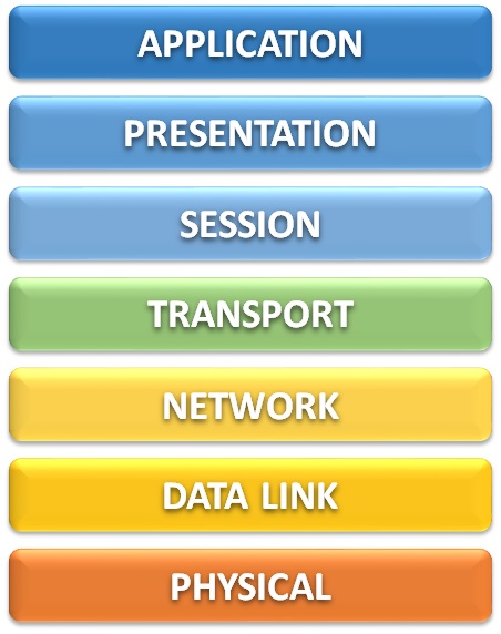
    This model can be broken down into two primary groupings – the Lower Layer (consisting of layers 1 through 4) and the Upper Layer (consisting of layers 5 through 7).

    The lower layers of the OSI model are the bread and butter of network administration.  These layers directly address how data flows across, into, and out of a network to other devices on that network or even out to the internet.

    On the other hand, the upper layers of the OSI model detail how that data is sent to and from the user’s application, as well as how that data is presented to the user – i.e., breaking down an email into multiple individual data packets, reassembling all of those packets in the correct order on the other side without losing any information, and presenting that email on the recipient’s inbox.

    Layer 7 – Application

    You could probably guess what this layer is, and you’d probably be right. The application layer consists of the programs that we as users interact with directly, such as web browsers or email clients. This also includes non-graphical network protocols which may be used from the command line or called in some other way (i.e., by the computer’s operating system) such as DHCP, FTP, and SNMP.

    Layer 6 – Presentation

    Presentation is a bang-on description of what the presentation layer does. This layer is responsible for the translation, compression, and encryption of application data before it is fed down to the lower-level layers, and again performs the reverse of these functions when fed receiving data by the session layer. The key benefit of this is that the presentation layer is in charge of ensuring that the recipient can understand what the sender is transmitting.

    Because not all data needs to go through a modification process to make data readable to a recipient, the presentation layer is sometimes skipped or otherwise performed by the application layer instead.

    Layer 5 – Session

    As data moves across the network, a conversation needs to be started between the sender and the receiver. This conversation is established, maintained, and eventually torn down by the session layer through the use of Application Program Interfaces (APIs). These APIs include NetBIOS, TCP/IP sockets, and Remote Procedure Calls (RPCs).

    The API conversations managed by the session layer differ from the TCP connections managed by the transport layer below in that the session layer manages these conversations on behalf of the application (the upper layers of the OSI model), whereas the transport layer manages its conversation on behalf of the network (the lower layers of the OSI model).

    Layer 4 – Transport

    Although I have already described the transport layer as one of the lower-level layers above, some of its functions could be said to be better described as upper-layer functions. If you look at all of the transport layer’s functionalities, though, it definitely skews more toward the lower (network) layers of the OSI model than the upper application layers.

    The transport layer primarily deals with the segmentation, packaging, and reassembly of data across the network through the connection-oriented Transmission Control Protocol (TCP) and connectionless User Datagram Protocol (UDP). It also insures the reliable delivery of quality network data by verifying that transmissions are received without errors and handling mismatches in speed to avoid overwhelming the receiver.

    Layer 3 – Network

    When I get asked what I do at work I usually try to summarize it somewhere along the lines of “I make sure that the computers can talk to each other.” The network layer is where the nuts and bolts of this communication really begin because this is where IP addresses come into play.

    Without an IP address — regardless of whether that is an IP version 4 address or an IP version 6 address — your computer isn’t going to get very far when attempting communication. When you attempt to browse to http://www.google.com, for instance, what really happens is that some DNS server translates the domain name (google.com) to an IP address (8.8.8.8).

    IP version 4 (IPv4) addresses consist of four sets of numbers between 0 and 255, called octets, which are separated by decimal points. There are public IP addresses which can be reached by anyone on the internet and private IP addresses which are reachable only from your local network. Of the private IP addresses, these are divided up into several groups known as classes — class A, class B, and class C being the most important. These directly relate to the maximum potential size for a network through something known as subnetting.

    IP version 6 (IPv6) addresses are much longer than IPv4 addresses and are made of up of hexadecimal characters — that is, numbers from 0 to 9 and letters from A to F. These addresses are 32 characters long and are broken up into eight groups called words which are separated by colons (:). They look something like this:

         2001:0db8:3333:4444:5555:6666:7777:8888

    Another very important function of the network layer is routing. Whatever your IP address is on your device, you will also have something called a gateway. If your computer is trying to communicate with another device outside of its subnet, then it will send that data to your gateway’s IP address. Your gateway will then route that traffic along the network based on its configuration.

    I may be a bit biased on this, but I feel like the data link layer is the most important of the lower layers.  This is where all the good stuff happens.  If the lower layers of the OSI model were a high school group project, layer 3 would be the jock that gets all the attention while layer 2 is the awkward kid that does all the actual work.

    Every device which connects to a network uses what is known as a Network Interface Controller, or NIC.  These NICs are technically a layer 1 component but they also contain what is arguably the most important component of the data link layer – a Media Access Control (MAC) Address.

    Each NIC has a MAC address which is assigned by the manufacturer.  (Sometimes these addresses are referred to as a burned-in address rather than a MAC address; it’s the same thing.)  These MAC addresses consist of 16 bits which are rendered in hexadecimal – that is, the only valid characters are 0 through 9, and A through F.

    MAC addresses can be presented in multiple logical formats which are usually divided into either six groups of two characters or three groups of four characters, often separated by a dot, colon, or hyphen.  The exact formatting of these MAC addresses doesn’t really matter too much.  They are written that way for much the same reason that phone numbers are written the way they are: for human benefit.  There are some exceptions to this in that the operating systems of network devices often require MAC addresses to be entered in a specific, consistent format.

    Layer 1 – Physical

    This layer consists of the physical wires and hardware necessary for computer networking.  That includes ethernet cables and network devices such as switches, routers, and firewalls.  Anything you can literally put your hands on, or any component piece of those such as internal electronics, is usually considered layer 1.

    Also included in layer 1 are the electrical impulses which are transmitted across the conductor wire, whether that is copper, fiber, or something else entirely.  (There is, I am given to understand, an actual RFC out there which defines the transmission of data across wet string, not to mention the well-known RFC for transmission by carrier pigeon.)

    Considerations

    In general, network traffic flows downward from Layer 7 to Layer 1 on the sending device, then upwards from Layer 1 to Layer 7 on the receiving device.  This is due to the way that operating systems break down application data into packets, frames, and ultimately the zeroes and ones which get transmitted across the wire.  Then, on the other side, the receiving device has to be able to know how to interpret those zeroes and ones, then reassemble them up the stack into application data.

    One thing to keep in mind is that the OSI model is not perfect.  It is a conceptual model.  You could visualize the OSI model as a 7-layer dip and not be entirely wrong.  Just like that same game day chip dip, you may not always hit every single layer in a single bite.  That’s okay.  Again…it’s a concept, not a ruleset.

  • Cisco ISE: Adding Network Devices

    In ISE, switches are referred to as a Network Access Device (NAD).  Other NAD devices include wireless LAN controllers and VPN concentrators.  NADs are responsible for enforcing ISE policies on devices connecting to the network with MAB authentication via RADIUS, as well as authorization of remote device administration over SSH via TACACS+.

    Before a switch will act as a NAD, it needs to be added to ISE as an object and configured for use as both a RADIUS and TACACS server with a shared key.

    To add a new switch to act as a NAD in ISE:

    1. Navigate to Administration > Network Resources > Network Devices.
    2. Click the + Add button.
    3. Configure the following attribute fields:
      1. Name: Type in the hostname of the switch.
      1. IP Address:         Type the management IP address of the switch.
      1. Location:            Click the drop-down and select Location.
      1. IPSEC:                 Click the drop-down and select Is IPSEC Device.
      1. Device Type:      Click the drop-down and select Device-Type.
    4. Click the checkbox next to RADIUS Authentication Settings and configure the Shared Secret.
    5. Click the checkbox next to TACACS Authentication Settings and configure the Shared Secret.
    6. Click the Submit button to complete the configuration.

    To edit the configuration of an existing device:

    1. Navigate to Administration > Network Resources > Network Devices.
    2. Click the checkbox next to the device to configure.
      Tip:  You can click the Show: drop down box and select Quick Filter option to search for a specific device using the Name or IP column.
    3. Click the Edit button.
  • Exam Review: Cisco SCOR 350-701

    I have been putting off writing this review for a year and a half now.  I did finally pass the SCOR exam and earn my CCNP Security certification, but only after four attempts and more hours than I care to try and estimate.  Don’t get me wrong – this is the first time I’ve ever framed a certification and hung it in my cubicle because I remember vividly what I went through to attain it.  I’m very happy and proud to have passed, but it seriously burned me out on studying for exams.

    After I passed the SISE exam in July of 2020, I immediately began studying for the SCOR exam.  My first attempt at it was in late September.  The next three attempts were all in the month of October, with my final passing result coming on October 24th.

    A major problem I had was specifically due to the official Cisco course guide being very scattered and irrelevant to the exam material, as well as my own lack of hands-on experience with any of the technologies covered by the exam apart from Identity Services Engine.  I also had some experience in studying for the retired IINS exam which included ASAs and VPNs, but I still do not have any experience with ESAs, WSAs, Umbrella, FirePOWER, or any of the other solutions covered by the SCOR.

    The greatest asset I had during my SCOR studies was a study group that was arranged by Martin B.(@martinmbne / mbne.net) for several of us who were all pursuing the CCNP Security certification.  We all shared our study notes, white papers we’d found, our wins, our losses, and they were a constant source of inspiration and motivation for me.  I would be remiss if I didn’t also mention Carl Zellers (@cfzellers4) and Kim Pedersen (@kpjungle / packet-forwarding.net) for offering their support and commiserations as I worked through my many exam attempts.

    Score Results

    This exam frustrated me for many reasons. One of those reasons is how close I came to passing on my second and third attempts. I’ve included the exam results of all of my attempts below for transparency.

    Exam TopicAttempt #1Attempt #2Attempt #3Attempt #4
    Security Concepts 80% 76% 84% 88%
    Network Security 52% 67% 67% 81%
    Securing the Cloud 67% 73% 80% 100%
    Content Security 64% 64% 71% 79%
    Endpoint Protection & Detection 70% 70% 50% 70%
    Secure Network Access, Visibility & Enforcement 80% 87% 80% 87%

    Study Materials and Cost

    For preparation, I used the following resources:

    CCNP and CCIE Security Core SCOR 350-701 Official Cert Guide (Cisco Press) – Cost: $73.60
    The nicest thing that I have to say about this book is that it I highly recommend it, at least as a starting point. You need to understand up front that this book does not do an adequate job of covering the exam material in enough detail — and honestly, doesn’t cover some exam material at all. You will not pass the SCOR exam solely by reading this book. If anything, my personal opinion is that this book gets you less than half the way there.

    Implementing and Operating Cisco Security Core Technologies (SCOR) v1.0 (Cisco Learning Library) – Cost:  $500
    Just like with the SISE exam, I’ve listed the retail cost here, but since I used Cisco learning credits this resource ended up being free to me.  I would still recommend it if you can afford it – or have learning credits available for use.  It makes a good companion to the printed materials and includes practice questions which aren’t carbon copies of those found in the OCG practice test.

    CCNP and CCIE Security Core SCOR 350-701 Complete Video Course (Pearson LiveLessons) – Cost: $129.89
    This video series is given by the same person who authored the OCG book, Omar Santos. I went into this with high expectations of exam-relevant content. If I had to do it again…I’m not sure I would invest in this product. About the only useful thing I got out of it were the practice test questions.

    Integrated Security Technologies and Solutions – Volume I: Cisco Security Solutions for Advanced Threat Protection with Next Generation Firewall, Intrusion Prevention, AMP, and Content Security (Cisco Press) – Cost: $56.28
    Integrated Security Technologies and Solutions – Volume II: Cisco Security Solutions for Network Access Control, Segmentation, Context Sharing, Secure Connectivity and Virtualization (Cisco Press) – Cost: $56.28
    After my second exam attempt, I think it was, these two books were recommended to me as resources by members of my study group. These are great resources. Again, you will not pass the exam with only these books, but I highly recommend them as a supplement to the OCG.

    Network Security Technologies and Solutions (Cisco Press) – Cost: $91.68
    I found this book on my own simply by browsing through the Cisco Press catalog of publications. It was not recommended to me, and I don’t believe anyone else in the study group used it. If you can afford to add this to your studies then I do recommend purchasing it. That said, if I had to choose only between this and the two volumes listed above, I’d pick those two.

    Exam Fees – Cost: $1,600.00
    Pretty self-explanatory here. Each exam attempt was $300, and I took it four times before I passed.

    In Retrospect…

    I spent a long time cursing the name of Omar Santos after this exam. I recently saw his name as one of the listed authors on a Cisco Press book that I was thinking about buying and immediately decided against it.

    In hindsight, I don’t know what kind of situation this exam was developed under…the material was the worst of any Cisco exam I have ever taken, but how closely did Cisco work to ensure that the material accurately reflected the exam?

    I don’t know, and I shouldn’t take that all out on Omar. I don’t even know the guy.

    My pockets are a lot lighter now and I’m fairly positive that I gained several new grey hairs (probably also lost a few permanently) as a result of this exam. But like I said before…I feel a great sense of accomplishment now that I have this certification, and I have gotten a fair amount of recognition from people I work with for having attained it.

    What’s Next?

    To be frank, I’m not really sure. I did take (and fail) the ENWLSD exam last year, mostly just because I thought it would be something quick and easy. I’m applying for some positions doing network security which require knowledge of Palo Alto firewalls and IPsec site-to-site VPNs, though, so I may pursue either the PCNSA or SVPN exams in order to bolster my knowledge with those solutions.

    I’m also roughly halfway through an associates degree program now which has severely limited my free time that I once used to study for certifications…but that’s not a terrible problem to have either.

  • SolarWinds Orion NPM: Configuring Cisco Hardware Health Pollers

    While troubleshooting an issue with a 4506 switch recently, I discovered an interesting discrepancy: Orion was reporting a critical hardware issue on the switch, but the switch itself didn’t seem to have any idea that anything was wrong.

    The exact error I was seeing was that a supply voltage sensor for a fiber switchport interface was in a critical state.

    A bit of Google-fu revealed multiple publications from the SolarWinds Customer Success Center which explained, in short, that Cisco devices may trigger false or invalid hardware health state alerts in the Orion Web Console due to a misconfiguration of the Hardware Health Poller settings.

    By default, it seems that Orion uses the CISCO-ENTITY-SENSOR-MIB.  The publications from SolarWinds state that this issue exists on the Cisco 3850 and 4500-series “and many more,” which is unhelpfully vague.  There is a link to another article hidden behind a login form that seems to insinuate that there is also a known problem with Cisco 3650 switches incorrectly reporting temperatures because of the same issue.

    The fix is to configure Orion to poll hardware health using the CISCO-ENVMON-MIB instead.  I attempted to research why this fixes the issue without much success.  The closest I got to finding a reason why the ENVMON MIB works when the ENTITY-SENSOR MIB does not was this sentence from an undated and deprecated Cisco document for the UBR series router:

    In Cisco IOS Release 12.2BC and later releases, use this MIB instead of CISCO-ENTITY-SENSOR-MIB for temperature monitoring.

    This seems to insinuate that the CISCO-ENTITY-SENSOR-MIB was deprecated following the release of Cisco IOS 12.2BC, but that’s largely an assumption on my part.  I have attempted further research without any success.

    The Resolution

    To reconfigure the Hardware Health Polling setting for a specific node, follow the steps below:

    1. Log into the Orion Web Console.
    2. Click Settings > Manage Nodes.
    3. Locate and select the desired node.
    4. Click Edit Properties.
    5. Scroll down to the Hardware Health Polling section near the bottom of the page.
    6. Click the Preferred Cisco MIB drop-down menu and select CISCO-ENVMON-MIB.
    7. Click Submit.

    At this point you can either wait for Orion to poll the node itself automatically or initiate a manual poll.  This should resolve the issue on the node.  However, if you would prefer to change the default behavior of Orion to use the ENVMON MIB instead, follow these steps:

    1. From the Orion Web Console, click on the Settings > All Settings menu.
    2. Find the Thresholds & Polling section, then click Polling Settings.
    3. Scroll down to the Hardware Health Polling section near the bottom of the page.
    4. Click the Preferred Cisco MIB drop-down menu and select CISCO-ENVMON-MIB.
    5. Click Submit.

    Alternatively there are two further workarounds that can be used if reconfiguring the MIB does not resolve the issue:

    • Disable the sensor(s)
    • Override the sensor(s)

    To override the sensor thresholds:

    1. From the Orion Web Console, click on the Settings > All Settings menu.
    2. Find the Node & Group Management section, then click Manage Hardware Sensors.
    3. Locate and select the desired sensor(s), then click Edit Thresholds.

    From this point, you can change the sensor status state and/or specify a new threshold.

    Additional Thoughts

    With no further information on whether this issue is caused by Cisco IOS version, hardware model, or both, I have elected to keep the global setting configured for its default value of CISCO-ENTITY-SENSOR-MIB and change the setting manually on a device-by-device basis until I have a better understanding of what exactly is going on.

    It would be helpful if someone – anyone – would publish some sort of guidance about the details of this issue.

    References

    Inaccurate Cisco hardware health is in warning or critical state | SolarWinds Customer Success Center
    https://support.solarwinds.com/SuccessCenter/s/article/Inaccurate-Cisco-hardware-health-is-in-warning-or-critical-state?language=en_US

    Change the preferred Cisco MIB for hardware health in NPM | SolarWinds Customer Success Center
    https://support.solarwinds.com/SuccessCenter/s/article/Change-the-preferred-Cisco-MIB-for-hardware-health-in-NPM?language=en_US

    Change the MIB used for polling hardware health statistics | SolarWinds Customer Success Center
    https://documentation.solarwinds.com/en/Success_Center/orionplatform/Content/Core-Changing-MIB-Used-for-Polling-Hardware-Health-Statistics-sw1607.htm

    Chapter 3, MIB Specifications | Cisco
    https://www.cisco.com/en/US/docs/ios/zz_trash/CableCmds/ubrmib3M.html#wp1029199

  • Wireshark Fundamentals: Setup and Configuration

    Wireshark Fundamentals: Setup and Configuration

    Wireshark is an open-source tool which is used to perform packet capture and analysis for wired or wireless network traffic.  It can be intimidating to look at the first time you open a packet capture file (or pcap).  Hopefully this introduction will help smooth the sharp edges on learning this tool.

    I was first introduced to network traffic analysis using Wireshark at a workshop taught by Brad Duncan during BSides Austin in 2019.  Brad maintains a website – Malware-Traffic-Analysis.net – where he posts tutorials on Wireshark as well as pcap files of real malware and ransomware infection network traffic.

    It’s important that I mention Brad Duncan here specifically because the first task is to set up the Wireshark display.  Brad has written several articles on this topic, and I did learn his preferred setup during the workshop I attended, so most of my preferences do stem from that experience.  There’s only a finite number of ways to configure Wireshark, especially for wired ethernet pcap files, and Brad’s method works very well.

    The only major difference between my preferences and Brad’s is that I choose to keep the packet number column.  I have personally found this column helpful when working on CTF challenges or when collaborating with another person to review a packet capture file.  (i.e., “Hey, can you check out packet 456 on file xyz? I think this might be C2 traffic.”)

    Once you understand the basics of configuring your display, it’s easy to create new profiles for specific use cases – such as if you’re investigating wireless traffic and want to see SSIDs or channel numbers listed, or if you’re investigating something that requires a specific set of custom fields such as HTTP host information.

    Summary of Instructions

    Install Wireshark:

    • Download Wireshark from wireshark.org/download.html.
    • Install the application; accept all default options and continue through each prompt until the installation is complete.
      • The installer will eventually ask if you would like to install USBPcap; it is not needed for anything covered here.
    • During the Npcap installation you will be presented with another list of options.  For now, click Install with nothing selected.
    • Once the installation is complete, launch the application to continue on with these configurations.

    Create a Configuration Profile:

    • On the top menu bar, navigate to Edit > Configuration Profiles to open the Configuration Profiles window.
    • Click the + (plus symbol) button to add a new profile entry.
    • Type a name in for your configuration profile.
      • What you name your profile is ultimately up to personal preference; I named mine 802.3 Wired Ethernet (unresolved).
    • Click OK to close the Configuration Profiles window.

    Configure Wireshark Column Displays:

    • Double-click one of your listed network adapters to open the packet inspection window, then immediately click the red square at the top left to stop packet capture.
    • Right click on any one of the display columns.
    • Click on Column Preferences…
    • Remove unnecessary columns:
      • Select the column entry titled Protocol, then click the
        – (minus symbol) button to remove it.
      • Select and remove the column entry titled Length.
    • Configure the Source columns:
      • Double-click and rename title Source to Source IP.
      • Double-click type Source address and change drop-down to Src addr (unresolved).
      • Use the + (plus symbol) button to add a new column entry with title Src Port and type Src port (unresolved).
      • Click and drag the new Src Port column field to just below Source IP.
    • Configure the Destination columns:
      • Double-click and rename title Destination to Destination IP.
      • Double-click type Destination address and change drop-down to Dest addr (unresolved).
      • Use the + (plus symbol) button to add a new column entry with title Dest Port and type Dest port (unresolved).
      • Click and drag the new Dest Port column field to just below Destination IP.
    • Click OK to exit the Preferences window.
    • On the menu bar, navigate to View > Time Display Format, then click UTC Date and Time of Day.

    Columns and Their Considerations

    Number

    The No. column is supremely useful for two things:

    • Referring to specific packets in a given capture file; and
    • Sorting packets back into the order of capture.

    I have never personally run into an instance where sorting by time/date has given me a reason for concern versus sorting by packet number, but a couple of blogs I looked at as I was drafting this article mentioned it, so I assume that this happens to people who use Wireshark for troubleshooting a lot more than I do.

    The real reason I insist on keeping this column is for collaborative use.  Very recently I participated in an OpenSOC event from Recon InfoSec where, during one of the challenges, my teammate was presented with a pair of pcap files as part of a reversing challenge he was working on.  One of the flags was to discover the first packet of command and control (or C2) traffic.  When he asked me to take a look at the files, I was able to identify what I thought was a good candidate, and give him the exact packet number so that he could take a look at what I was seeing.

    Date and Time

    Wireshark uses Seconds Since Beginning of Capture as its time display by default, which is honestly next to useless for any kind of corroboration against other datasets – or even retrospective analysis if you save a pcap file for later.  

    There are two great options for how to configure this:

    • Use UTC Date and Time of Day, which is my usual default; or
    • Date and Time of Day (without the UTC).

    As you can probably guess they are two sides of the same coin.  I don’t do a lot of my own packet captures; typically I’m looking at someone else’s pcap file, so the absolute local time doesn’t usually matter to me very much.  UTC time is something I’ve grown comfortable with seeing simply from other facets of IT work.

    In either case, Wireshark uses the system kernel of the machine capturing the traffic as the time source so it is important when capturing critical data to ensure that your system time is synchronized to an accurate source.  You can also switch between UTC and non-UTC display at any time on a given pcap file if it is pertinent to your investigation.

    There is an option in this same window to configure the granularity of the timestamps (seconds, tenths of a second, hundredths of a second, etc.) but in most cases you can leave this selection on the default setting — Automatic (from capture file).  For brevity’s sake it can clean up your display to use Seconds instead.  If you’re getting to the point where this matters for anything other than personal preference then you’re probably beyond the scope of this article anyway.

    Source and Destination IPs/Ports

    Even though Wireshark does show the source and destination IPs for captured packets by default, I find it incredibly useful to include the source and destination port numbers as well.  In cases where there is no layer 3 traffic (such as ARP), these fields will display MAC addresses instead, so you can still understand the source and destination traffic.

    In this article I have specified the use of unresolved IP addresses and port numbers.  Depending on your needs, it may make sense to set these to resolved. I’ve made myself both a resolved and an unresolved profile so that I can switch between the two as needed.

    One thing to keep an eye out for with resolving port numbers to a well-known name is that, sometimes, that traffic over UDP port 53 is not actually DNS traffic.  In one CTF that I participated in, the hostile C2 traffic was egressing the LAN from a random ephemeral port as you might expect, but the packet was an HTTP GET request of an obfuscated string to a remote IP over port 80.  Wireshark can’t always intelligently decode non-typical traffic like that and assign a resolved port name correctly.

    References

    Changing the Column Display in Wireshark  | Brad Duncan’s Malware Traffic Analysis
    https://www.malware-traffic-analysis.net/tutorials/wireshark/index.html

    Customizing Wireshark — Changing Your Custom Display  | Brad Duncan for Palo Alto Networks Unit 42 Blog
    https://unit42.paloaltonetworks.com/unit42-customizing-wireshark-changing-column-display/

    Wireshark Column Setup Deepdive  | Jasper at Packet-Foo
    https://blog.packet-foo.com/2018/08/wireshark-column-setup-deepdive/comment-page-1/

    SharkTIPS! My Favorite Wireshark Customizations (Part 1)  | Eddie Forero’s Bad-fi Blog
    https://badfi.com/blog/2017/5/16/sharktip-1

    Wireshare User Guide 7.6 – Time Stamps  | Wireshark.org
    https://www.wireshark.org/docs/wsug_html_chunked/ChAdvTimestamps.html

  • Reset Configurations on a Cisco Switch

    There are several instances where you may need to reset a Cisco switch back to a blank configuration.  Perhaps you purchased a switch for your home lab off of the internet and it didn’t get wiped before it got sent out to you; or perhaps your company acquired a new contract at an existing property where the old tenant left behind their network hardware but did not provide any of the access information.

    The process below assumes that you, like me, want to keep the old configuration files.  You could theoretically delete these instead of renaming them instead.

    Summary

    • Begin from an unpowered state with power cable unplugged from the switch
    • Plug in power cable while holding down MODE button to interrupt boot sequence
    • Enter “flash_init” to initialize flash memory
    • Enter “rename flash:config.text flash:config-old.text” to remove startup config
    • Enter “rename flash:private-config.text flash:private-old.text” to remove VLANs
    • Enter “boot” to initiate the device boot sequence
    • Enter “no” to the initial configuration dialog
    • Enter “copy running-config startup-config” to create a new blank startup config

    CLI in Full

    C2950 Boot Loader (C2950-HBOOT-M) Version 12.1(11r)EA1, RELEASE SOFTWARE (fc1)
    Compiled Mon 22-Jul-02 17:18 by antonino
    WS-C2950T-24 starting...
    Base ethernet MAC Address: 00:0c:ce:22:a7:c0
    Xmodem file system is available.
    
    The system has been interrupted prior to initializing the
    flash filesystem.  The following commands will initialize
    the flash filesystem, and finish loading the operating
    system software:
    
        flash_init
        load_helper
        boot
    
    switch: flash_init
    Initializing Flash...
    flashfs[0]: 329 files, 5 directories
    flashfs[0]: 0 orphaned files, 0 orphaned directories
    flashfs[0]: Total bytes: 7741440
    flashfs[0]: Bytes used: 5651456
    flashfs[0]: Bytes available: 2089984
    flashfs[0]: flashfs fsck took 7 seconds.
    ...done initializing flash.
    Boot Sector Filesystem (bs:) installed, fsid: 3
    Parameter Block Filesystem (pb:) installed, fsid: 4
    
    switch: dir flash:
    Directory of flash:/
    
    2    -rwx 112       <date>     info
    3    -rwx 3722814   <date>     c2950-i6k2l2q4-mz.121-22.EA14.bin
    4    drwx 4416      <date>     html
    331  -rwx 112       <date>     info.ver
    332  -rwx 316       <date>     env_vars
    333  -rwx 1343      <date>     config.text
    334  -rwx 24        <date>     private-config.text
    
    2089984 bytes available (5651456 bytes used)
    
    switch: rename flash:config.text flash:config-old.text
    switch: dir flash:
    Directory of flash:/
    
    2    -rwx 112       <date>     info
    3    -rwx 3722814   <date>     c2950-i6k2l2q4-mz.121-22.EA14.bin
    4    drwx 4416      <date>     html
    331  -rwx 112       <date>     info.ver
    332  -rwx 316       <date>     env_vars
    333  -rwx 1343      <date>     config-old.text
    334  -rwx 24        <date>     private-config.text
    
    2089984 bytes available (5651456 bytes used)
    
    switch: rename flash:private-config.text flash:private-old.text
    switch: dir flash:
    Directory of flash:/
    
    2    -rwx 112       <date>     info
    3    -rwx 3722814   <date>     c2950-i6k2l2q4-mz.121-22.EA14.bin
    4    drwx 4416      <date>     html
    331  -rwx 112       <date>     info.ver
    332  -rwx 316       <date>     env_vars
    333  -rwx 1343      <date>     config-old.text
    334  -rwx 24        <date>     private-old.text
    
    2089984 bytes available (5651456 bytes used)
    
    switch: boot
    Loading "flash:c2950-i6k2l2q4-mz.121-22.EA14.bin"...
    
             --- System Configuration Dialog ---
    
    Would you like to enter the initial configuration dialog? [yes/no]:no
    00:00:16: %SPANTREE-5-EXTENDED_SYSID: Extended SysId enabled for type vlan
    00:00:20: %SYS-5-RESTART: System restarted --
    Cisco Internetwork Operating System Software
    IOS (tm) C2950 Software (C2950-I6K2L2Q4-M), Version 12.1(22)EA14, RELEASE SOFTWARE (fc1)
    Technical Support: http://www.cisco.com/techsupport
    Copyright (c) 1986-2010 by cisco Systems, Inc.
    Compiled Tue 26-Oct-10 10:35 by nburra
    00:00:20: %SNMP-5-COLDSTART: SNMP agent on host Switch is undergoing a cold start
    
    
    Press RETURN to get started!
    
    
    Switch>
    00:00:48: %LINK-5-CHANGED: Interface Vlan1, changed state to administratively down
    Switch> enable
    Switch# show startup-config
    startup-config is not present
    Switch# copy running-config startup-config
    Destination filename [startup-config]?
    Building configuration...
    [OK]
    Switch#

    Tested and confirmed first-hand on the following switch models:   Cisco WS-C2950T-24, WS-C2960-24TC-L, WS-C3560-48PS-S

  • Hands-On With the Ubiquiti USG-PRO-4: Year 1

    In July of 2018, exactly a year ago, I was looking for just about any reason at all to pull the trigger on a firewall device for my home network and found myself split between the Meraki MX series, the Fortinet FortiGate line, or one of the two Ubiquiti USG options available at the time. (more…)

  • Configuring Secure DNS Over HTTPS With Pi-Hole

    Sometime last year, I ran across a post on Twitter talking about this thing called a Pi-Hole which could be used as a secure DNS server, automatically blocking adware and — potentially — malicious traffic. I remember thinking to myself oh, that’s cool, and I even went to text a screencap of the post to a friend out of state, but then I promptly forgot about it for 4 or 5 months.

    (more…)

  • Setting Up GNS3, Part I: Initial Configuration

    When I began looking at the world of Cisco certifications, I was overwhelmed by the sheer amount of material there was to learn.  Sure, I went at the CCENT with a baseline knowledge of networking gained from the CompTIA Network+ (and some associated concepts from the Security+), but not everything on the exam is listed on the objectives.

    Case in point: establishing a home lab environment. (more…)