Networking is one of the fundamental pillars of computing. Networks allow us to communicate data across a global scale in a way which largely seems (to me) to be taken for granted. Networking, even on the most basic of levels, is a skill that will aid anyone in technology will find valuable to their career – from system administrators, to help desk, to programmers.
I will be starting off with a simple description of what networking is, then going through some basic terminology, introducing the OSI model, describing local versus routable network traffic, some basic network troubleshooting tools, and finally ending with a high-level overview of some of the most basic network protocols such as HTTP and DNS.
My hope is that – even if I don’t inspire the same level of interest in you that I have with networking – you do come away learning something.
What is Networking?
Networks allow two devices to talk to each other and transmit application data, whether they’re as close together as being in the same room or as far as being half a world apart. Accomplishing this involves a basic, standardized process for how two devices – with no prior knowledge of the other’s location – can send information back and forth.
At its highest level, the Internet is a network. This is the one network that I’m sure everyone reading this post is aware of. On a more granular level, though, a network can be as small as a Bluetooth device connecting to your phone (known as a Personal Area Network, or PAN). If you have a modem or router at home that allows multiple devices to connect through your Internet Service Provider, you have a Local Area Network (LAN).
In order to accomplish this, we use network devices. The most common of these are the switch and the router. Earlier devices like hubs and bridges did once exist, but have mostly gone the way of the dinosaur. The primary differences between these devices is found in how they handle network communications, also known as traffic.
Switches aggregate incoming traffic from each physical port (also known as an interface) and forward it on to its destination. If the intended recipient is directly connected to the same switch as the sending device, then the switch will forward that traffic directly from the sender to the destination device. If the recipient is not directly connected to the same switch as the sending device then one of two things happens:
- The switch has learned where the recipient is connected on a neighboring network device (switch or router) and forwards that traffic to the neighboring network device; or
- The switch has never seen the intended recipient before, does not know where it is located on the network, and sends the traffic out of every interface except the interface that traffic was received on. This is known as a flood.
Routers, on the other hand, are meant to take network traffic from switches destined to a different network than the originating network. As an example, if you were to open a web browser and open google.com, your network router would take that traffic and forward it out to the internet for Google’s network to respond to. I will get more into this a little further down when I go over local versus routable network addressing.
Some routers – either home routers which are manufactured this way or business-class routers which are specifically configured this way – can service the same network from multiple interfaces. For the sake of simplifying things in this post I will refer to routers specifically when traffic needs to be forwarded between two separate networks.
The OSI Model
When dealing with an abstract principle such as networking, it is helpful to have a logical representation to visualize concepts. This is where the OSI model comes in.
Back in the late 70s, work began on multiple fronts to establish a standard model for networks which resulted in several publications. Possibly the most well-known of these is the Open Systems Interconnection – Basic Reference Model, colloquially known as the OSI model. This was, according to Wikipedia anyway, first defined in 1978 by Hubert Zimmerman before being published in 1984 by the International Standards Organization as standard ISO 7498. It is regularly referenced in day-to-day network administration and is one of the most important basic principles to learn in networking as a whole.
I would be remiss at this point if I did not also mention the Internet Protocol Suite, also known as TCP/IP, but sometimes also referred to as the TCP/IP model. The Internet Protocol Suite is not really a model so much as it is an architecture which specifies how data is packetized, addressed, transmitted, routed, and received over a network. Comparing the TCP/IP architecture with the OSI model is a bit of a nonstarter simply because they are two sides of the same coin. Each compliments and builds upon the other. Both share some of the same principles. The most important difference is that the OSI model provides a more comprehensive breakdown of networking concepts while TCP/IP focuses on the nuts and bolts of implementing various protocols.
The OSI model consists of seven layers arranged vertically in a stack, beginning on the bottom with Layer 1 and ending at the top with Layer 7. These layers logically organize networking principles into separate groups in a way that is relatively easy to comprehend. By understanding each of these layers, we can begin understanding both how TCP/IP architecture functions, as well as methodologies for troubleshooting connectivity when issues arise.
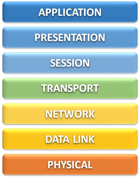
This model can be broken down into two primary groupings – the Lower Layer (consisting of layers 1 through 4) and the Upper Layer (consisting of layers 5 through 7).
The lower layers of the OSI model are the bread and butter of network administration. These layers directly address how data flows across, into, and out of a network to other devices on that network or even out to the internet.
On the other hand, the upper layers of the OSI model detail how that data is sent to and from the user’s application, as well as how that data is presented to the user – i.e., breaking down an email into multiple individual data packets, reassembling all of those packets in the correct order on the other side without losing any information, and presenting that email on the recipient’s inbox.
Layer 7 – Application
You could probably guess what this layer is, and you’d probably be right. The application layer consists of the programs that we as users interact with directly, such as web browsers or email clients. This also includes non-graphical network protocols which may be used from the command line or called in some other way (i.e., by the computer’s operating system) such as DHCP, FTP, and SNMP.
Layer 6 – Presentation
Presentation is a bang-on description of what the presentation layer does. This layer is responsible for the translation, compression, and encryption of application data before it is fed down to the lower-level layers, and again performs the reverse of these functions when fed receiving data by the session layer. The key benefit of this is that the presentation layer is in charge of ensuring that the recipient can understand what the sender is transmitting.
Because not all data needs to go through a modification process to make data readable to a recipient, the presentation layer is sometimes skipped or otherwise performed by the application layer instead.
Layer 5 – Session
As data moves across the network, a conversation needs to be started between the sender and the receiver. This conversation is established, maintained, and eventually torn down by the session layer through the use of Application Program Interfaces (APIs). These APIs include NetBIOS, TCP/IP sockets, and Remote Procedure Calls (RPCs).
The API conversations managed by the session layer differ from the TCP connections managed by the transport layer below in that the session layer manages these conversations on behalf of the application (the upper layers of the OSI model), whereas the transport layer manages its conversation on behalf of the network (the lower layers of the OSI model).
Layer 4 – Transport
Although I have already described the transport layer as one of the lower-level layers above, some of its functions could be said to be better described as upper-layer functions. If you look at all of the transport layer’s functionalities, though, it definitely skews more toward the lower (network) layers of the OSI model than the upper application layers.
The transport layer primarily deals with the segmentation, packaging, and reassembly of data across the network through the connection-oriented Transmission Control Protocol (TCP) and connectionless User Datagram Protocol (UDP). It also insures the reliable delivery of quality network data by verifying that transmissions are received without errors and handling mismatches in speed to avoid overwhelming the receiver.
Layer 3 – Network
When I get asked what I do at work I usually try to summarize it somewhere along the lines of “I make sure that the computers can talk to each other.” The network layer is where the nuts and bolts of this communication really begin because this is where IP addresses come into play.
Without an IP address — regardless of whether that is an IP version 4 address or an IP version 6 address — your computer isn’t going to get very far when attempting communication. When you attempt to browse to http://www.google.com, for instance, what really happens is that some DNS server translates the domain name (google.com) to an IP address (8.8.8.8).
IP version 4 (IPv4) addresses consist of four sets of numbers between 0 and 255, called octets, which are separated by decimal points. There are public IP addresses which can be reached by anyone on the internet and private IP addresses which are reachable only from your local network. Of the private IP addresses, these are divided up into several groups known as classes — class A, class B, and class C being the most important. These directly relate to the maximum potential size for a network through something known as subnetting.
IP version 6 (IPv6) addresses are much longer than IPv4 addresses and are made of up of hexadecimal characters — that is, numbers from 0 to 9 and letters from A to F. These addresses are 32 characters long and are broken up into eight groups called words which are separated by colons (:). They look something like this:
2001:0db8:3333:4444:5555:6666:7777:8888Another very important function of the network layer is routing. Whatever your IP address is on your device, you will also have something called a gateway. If your computer is trying to communicate with another device outside of its subnet, then it will send that data to your gateway’s IP address. Your gateway will then route that traffic along the network based on its configuration.
Layer 2 – Data Link
I may be a bit biased on this, but I feel like the data link layer is the most important of the lower layers. This is where all the good stuff happens. If the lower layers of the OSI model were a high school group project, layer 3 would be the jock that gets all the attention while layer 2 is the awkward kid that does all the actual work.

Every device which connects to a network uses what is known as a Network Interface Controller, or NIC. These NICs are technically a layer 1 component but they also contain what is arguably the most important component of the data link layer – a Media Access Control (MAC) Address.
Each NIC has a MAC address which is assigned by the manufacturer. (Sometimes these addresses are referred to as a burned-in address rather than a MAC address; it’s the same thing.) These MAC addresses consist of 16 bits which are rendered in hexadecimal – that is, the only valid characters are 0 through 9, and A through F.
MAC addresses can be presented in multiple logical formats which are usually divided into either six groups of two characters or three groups of four characters, often separated by a dot, colon, or hyphen. The exact formatting of these MAC addresses doesn’t really matter too much. They are written that way for much the same reason that phone numbers are written the way they are: for human benefit. There are some exceptions to this in that the operating systems of network devices often require MAC addresses to be entered in a specific, consistent format.
Layer 1 – Physical
This layer consists of the physical wires and hardware necessary for computer networking. That includes ethernet cables and network devices such as switches, routers, and firewalls. Anything you can literally put your hands on, or any component piece of those such as internal electronics, is usually considered layer 1.
Also included in layer 1 are the electrical impulses which are transmitted across the conductor wire, whether that is copper, fiber, or something else entirely. (There is, I am given to understand, an actual RFC out there which defines the transmission of data across wet string, not to mention the well-known RFC for transmission by carrier pigeon.)
Considerations
In general, network traffic flows downward from Layer 7 to Layer 1 on the sending device, then upwards from Layer 1 to Layer 7 on the receiving device. This is due to the way that operating systems break down application data into packets, frames, and ultimately the zeroes and ones which get transmitted across the wire. Then, on the other side, the receiving device has to be able to know how to interpret those zeroes and ones, then reassemble them up the stack into application data.
One thing to keep in mind is that the OSI model is not perfect. It is a conceptual model. You could visualize the OSI model as a 7-layer dip and not be entirely wrong. Just like that same game day chip dip, you may not always hit every single layer in a single bite. That’s okay. Again…it’s a concept, not a ruleset.

